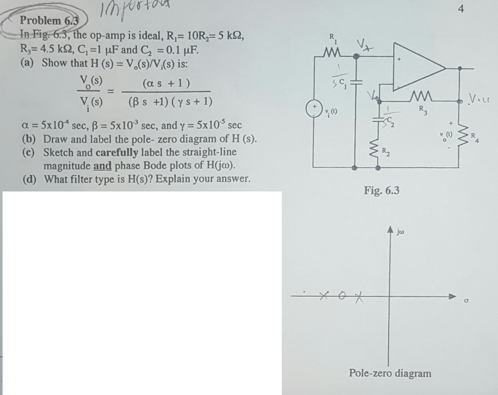
20+ How To Sketch Bode Plots Pics. First supplemental lecture video on how to sketch bode plots. It is usually a combination of a bode magnitude plot, expressing the magnitude (usually in decibels) of the frequency response, and a bode phase plot, expressing the phase shift.

A sketch of the log magnitude of h( jω) versus logω and a sketch of the angle of h( jω) versus logω.
For ω > ωc, the (ω/ωc)2 dominates the magnitude expression, allowing us to approximate the magnitude as 20 log. A bode plot is a standard format for plotting frequency response of lti systems. • read sections 6.1 through 6.6, except for the nyquist criterion. For ω > ωc, the (ω/ωc)2 dominates the magnitude expression, allowing us to approximate the magnitude as 20 log.